Search Results for power lines
Explore AI generated designs, images, art and prompts by top community artists and designers.
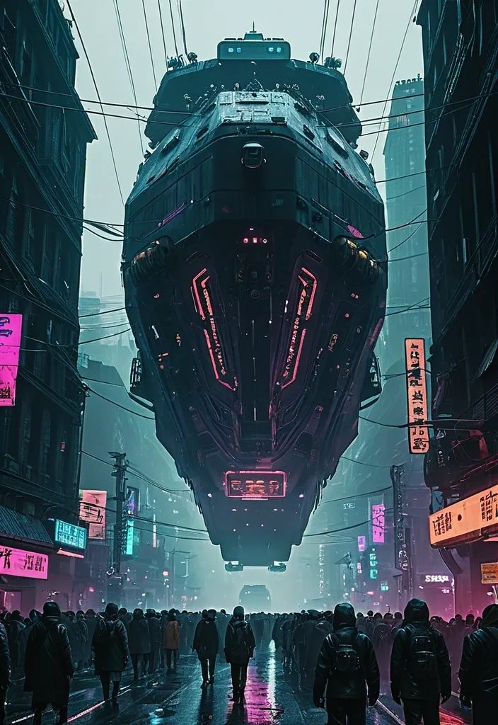

A dystopian urban scene depicting a massive , futuristic transport vessel (vessel:1.2) hovering above a bustling street filled with crowds of people in rugged attire. The setting is drenched in a moody , atmospheric haze , illuminated by neon signs (neon:1.2) in various languages. The composition focuses on the interplay between the imposing vessel and the crowd below , emphasizing scale and technology contrast. Use a desaturated color palette to enhance the grim ambience , with sharp focal depth highlighting both foreground and background details. Capture the essence of cyberpunk with intricate architectural elements and power lines (details:1.3). Avoid bright , cheerful colors or idyllic settings to maintain the atmospheric tension (negative: bright colors). ,

A sunny afternoon in a small Japanese town during cherry blossom season. A teenage girl in a school uniform walks her bicycle along a tree-lined path covered in pink petals. Traditional houses , power lines , and a cat lounging on a wall complete the peaceful scene. Soft pastel colors , anime art style , warm and nostalgic atmosphere. ,
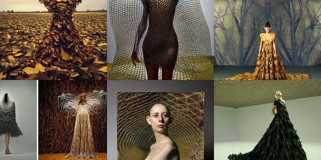


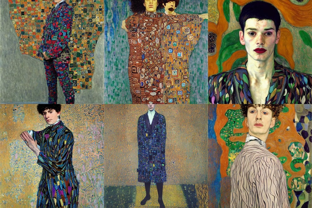
nonbinary person wearing suit made of leaves , art by Gustav Klimt , art by Jenny Saville , art by Domenikos Theotokopoulos , art by Henri Matisse , art by Rembrandt Van Rijn , art by Michelangelo Buonarroti , art by Piet Mondrian , art by Tiziano Vecellio Di Gregorio , rougish , power lines , art by Paul Gauguin , intricate picture frame , art by Edward Hopper , art by Francis Bacon , and Shinkai Makoto , venice style , art by Gustav Klimt , art by Vincent Van Gogh ,
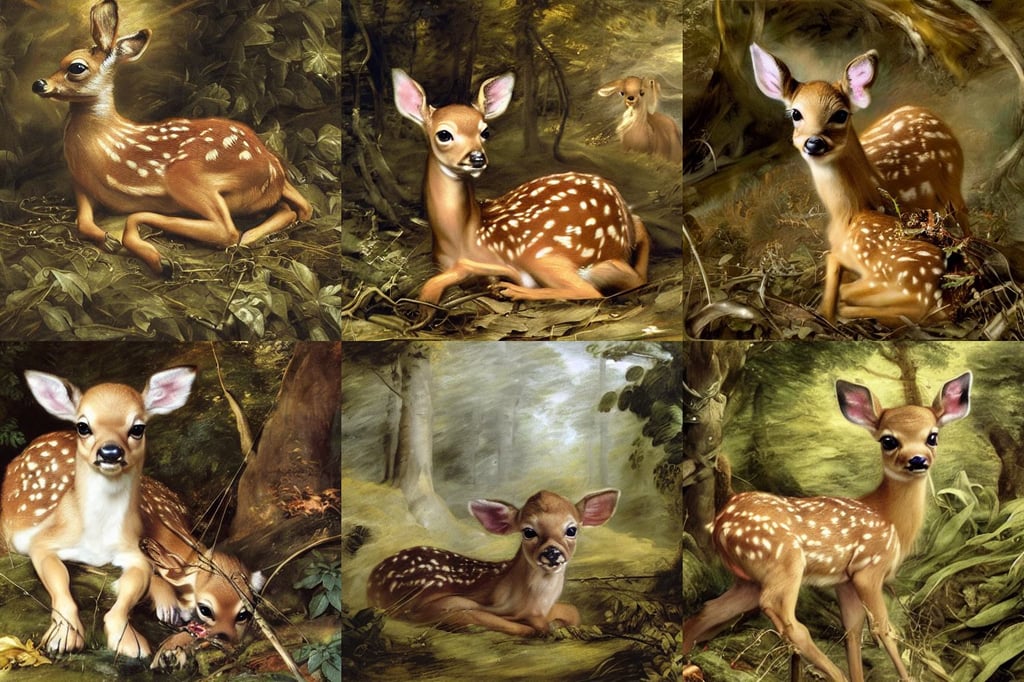
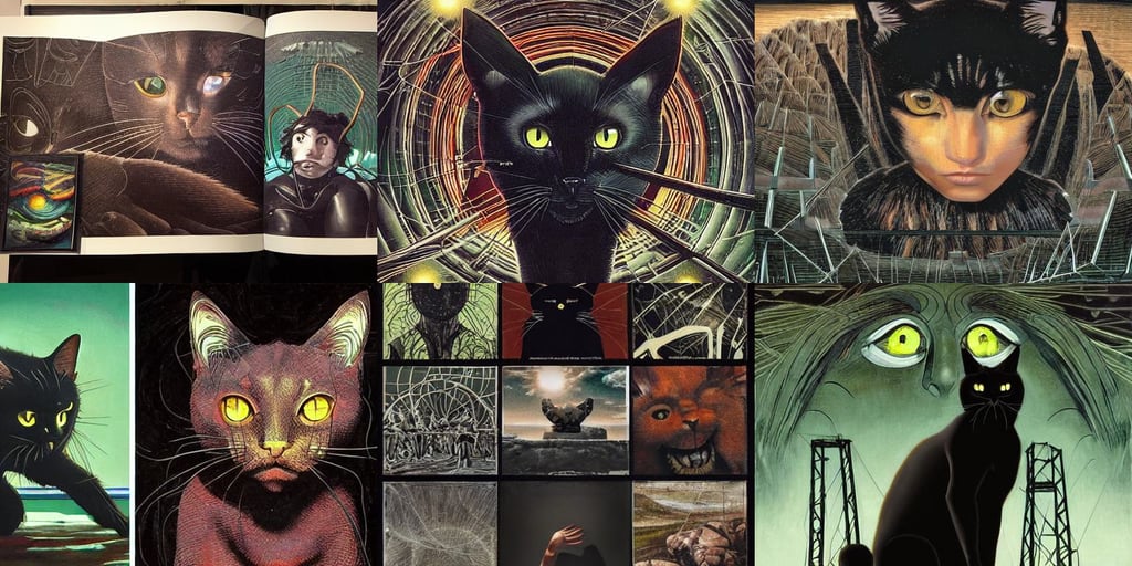
cute fawn curled up on the forest floor , power lines , art by Sir Peter Paul Rubens , octane render , art by Francisco De Goya , detailed mechanical features , art by Tommaso Masaccio , character creation , art by Gerhard Richter , art by Diego Velázquez , fantasy , insanely detailed and intricate , with Muppets , pastell yellow tones ,

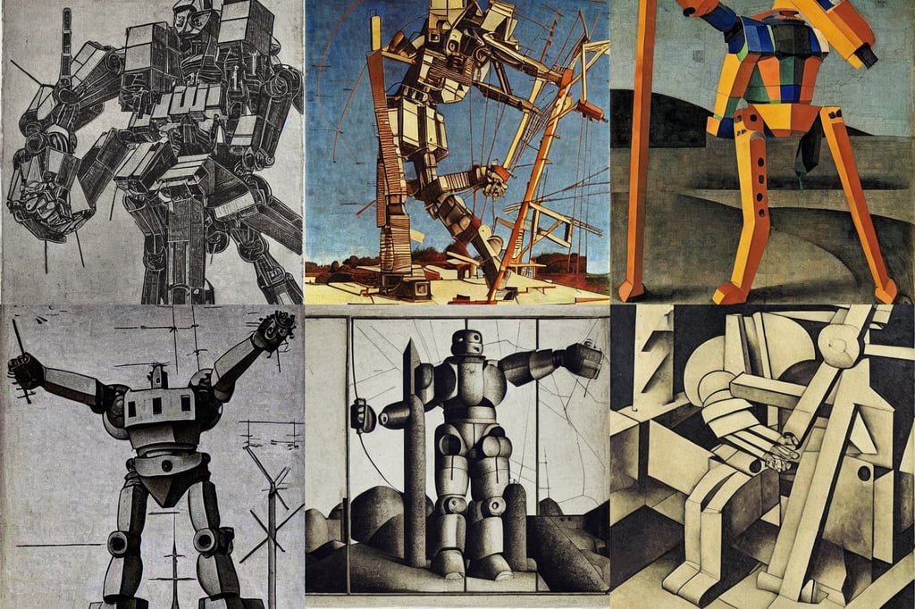
Natalie Portman as Aztec princess , art by Jenny Saville , Alex Grey , mexico , art by Kazimir Malevich , brutalism , art by Marcel Duchamp , art by Tiziano Vecellio Di Gregorio , sharp focus , Set in the Rocky Mountains , art by Winslow Homer , power lines , art by Jenny Saville , art by Henri Matisse , 35mm octane render ,
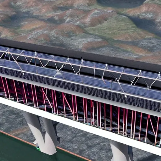
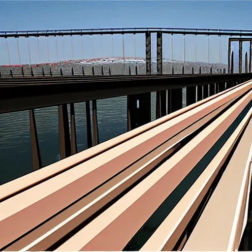
3.Bridge Configuration 1.The bridge may cross the valley at any elevation from the high water level that you can assume to 24 meters above the high water level. 2.If the elevation of the bridge is below 24 meters , excavation of the river banks will be required to achieve the correct highway elevation. 3.To provide clearance for overhead power lines (shown above) , the highest point on the bridge may not exceed an elevation 32.5 meters above the high water level (8.5 meters above the top of the river banks). 4.The bridge may consist of either standard (simple supports) or (arch supports). If necessary , the bridge may also use one intermediate , located near the centre of the valley. If necessary , the bridge may also use cable , located 8 meters behind one or both abutments. 5.Each main truss can have no more than 100 and no more than 200 . 6.The bridge will have a flat , reinforced deck. Two types of concrete are available: 1.Medium-strength concrete requires a deck thickness of 23 centimetres (0.23 metres). 2.High-strength concrete requires a deck thickness of 15 centimetres (0.15 meter). 7.In either case , the deck will be supported by transverse spaced at 4 metre intervals. To accommodate these floor beams , your must have a row of joints spaced 4 meters apart at the level of the deck. These joints are created automatically when you begin a new design. 8.The bridge deck will be 10 meters wide , such that it can accommodate two lanes of traffic. 4.Member Properties •Materials. Each member of the truss will be made of either carbon steel , high-strength low-alloy steel , or quenched and tempered steel. •. The members of the truss can be either solid bars or hollow tubes. Both types of cross-sections are square. •Member Size. Both cross-sections are available in a variety of standard sizes. 5.Loads The bridge must be capable of safely carrying the following loads: •Weight of the deck. •Weight of a 5-cm thick , which might be applied at some time in the future. •Weight of the steel floor beams and supplemental bracing members (assumed to be 12.0 applied at each deck-level joint). •Weight of the main trusses. •Either of two possible truck loadings: Weight of one standard H25 truck loading per lane , including appropriate allowance for the dynamic effects of the moving load. (Since the bridge carries two lanes of traffic , each main truss must safely carry one H25 vehicle , placed anywhere along the length of the deck.) Weight of a single 480 kN Permit Loading , including appropriate allowance for the dynamic effects of the moving load. (Since the Permit Loading is assumed to be cantered laterally , each main truss must safely carry one-half of the total vehicle weight , placed anywhere along the length of the deck.) ,
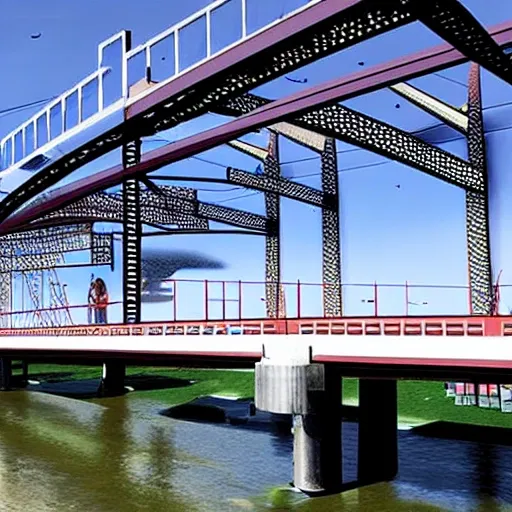
3.Bridge Configuration 1.The bridge may cross the valley at any elevation from the high water level to 24 meters above the high water level. 2.If the elevation of the bridge is below 24 meters , excavation of the river banks will be required to achieve the correct highway elevation. 3.To provide clearance for overhead power lines (shown above) , the highest point on the bridge may not exceed an elevation 32.5 meters above the high water level (8.5 meters above the top of the river banks). 4.The bridge may consist of either standard (simple supports) or (arch supports). If necessary , the bridge may also use one intermediate , located near the centre of the valley. If necessary , the bridge may also use cable , located 8 meters behind one or both abutments. 5.Each main truss can have no more than 100 and no more than 200 . 6.The bridge will have a flat , reinforced deck. Two types of concrete are available: 1.Medium-strength concrete requires a deck thickness of 23 centimetres (0.23 metres). 2.High-strength concrete requires a deck thickness of 15 centimetres (0.15 meter). 7.In either case , the deck will be supported by transverse spaced at 4 metre intervals. To accommodate these floor beams , your must have a row of joints spaced 4 meters apart at the level of the deck. These joints are created automatically when you begin a new design. 8.The bridge deck will be 10 meters wide , such that it can accommodate two lanes of traffic. 4.Member Properties •Materials. Each member of the truss will be made of either carbon steel , high-strength low-alloy steel , or quenched and tempered steel. •. The members of the truss can be either solid bars or hollow tubes. Both types of cross-sections are square. •Member Size. Both cross-sections are available in a variety of standard sizes. 5.Loads The bridge must be capable of safely carrying the following loads: •Weight of the deck. •Weight of a 5-cm thick , which might be applied at some time in the future. •Weight of the steel floor beams and supplemental bracing members (assumed to be 12.0 applied at each deck-level joint). •Weight of the main trusses. •Either of two possible truck loadings: Weight of one standard H25 truck loading per lane , including appropriate allowance for the dynamic effects of the moving load. (Since the bridge carries two lanes of traffic , each main truss must safely carry one H25 vehicle , placed anywhere along the length of the deck.) Weight of a single 480 kN Permit Loading , including appropriate allowance for the dynamic effects of the moving load. (Since the Permit Loading is assumed to be cantered laterally , each main truss must safely carry one-half of the total vehicle weight , placed anywhere along the length of the deck.) ,
architecture Bridge Configuration 1.The bridge may cross the valley at any elevation from the high water level to 24 meters above the high water level. 2.If the elevation of the bridge is below 24 meters , excavation of the river banks will be required to achieve the correct highway elevation. 3.To provide clearance for overhead power lines (shown above) , the highest point on the bridge may not exceed an elevation 32.5 meters above the high water level (8.5 meters above the top of the river banks). 4.The bridge may consist of either standard (simple supports) or (arch supports). If necessary , the bridge may also use one intermediate , located near the centre of the valley. If necessary , the bridge may also use cable , located 8 meters behind one or both abutments. 5.Each main truss can have no more than 100 and no more than 200 . 6.The bridge will have a flat , reinforced deck. Two types of concrete are available: 1.Medium-strength concrete requires a deck thickness of 23 centimetres (0.23 metres). 2.High-strength concrete requires a deck thickness of 15 centimetres (0.15 meter). 7.In either case , the deck will be supported by transverse spaced at 4 metre intervals. To accommodate these floor beams , your must have a row of joints spaced 4 meters apart at the level of the deck. These joints are created automatically when you begin a new design. 8.The bridge deck will be 10 meters wide , such that it can accommodate two lanes of traffic. 4.Member Properties •Materials. Each member of the truss will be made of either carbon steel , high-strength low-alloy steel , or quenched and tempered steel. •. The members of the truss can be either solid bars or hollow tubes. Both types of cross-sections are square. •Member Size. Both cross-sections are available in a variety of standard sizes. ,
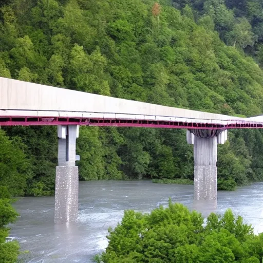
Bridge Configuration 1.The bridge may cross the valley at any elevation from the high water level to 24 meters above the high water level. 2.If the elevation of the bridge is below 24 meters , excavation of the river banks will be required to achieve the correct highway elevation. 3.To provide clearance for overhead power lines (shown above) , the highest point on the bridge may not exceed an elevation 32.5 meters above the high water level (8.5 meters above the top of the river banks). 4.The bridge may consist of either standard (simple supports) or (arch supports). If necessary , the bridge may also use one intermediate , located near the centre of the valley. If necessary , the bridge may also use cable , located 8 meters behind one or both abutments. 5.Each main truss can have no more than 100 and no more than 200 . 6.The bridge will have a flat , reinforced deck. Two types of concrete are available: 1.Medium-strength concrete requires a deck thickness of 23 centimetres (0.23 metres). 2.High-strength concrete requires a deck thickness of 15 centimetres (0.15 meter). 7.In either case , the deck will be supported by transverse spaced at 4 metre intervals. To accommodate these floor beams , your must have a row of joints spaced 4 meters apart at the level of the deck. These joints are created automatically when you begin a new design. 8.The bridge deck will be 10 meters wide , such that it can accommodate two lanes of traffic. 4.Member Properties •Materials. Each member of the truss will be made of either carbon steel , high-strength low-alloy steel , or quenched and tempered steel. •. The members of the truss can be either solid bars or hollow tubes. Both types of cross-sections are square. •Member Size. Both cross-sections are available in a variety of standard sizes. ,
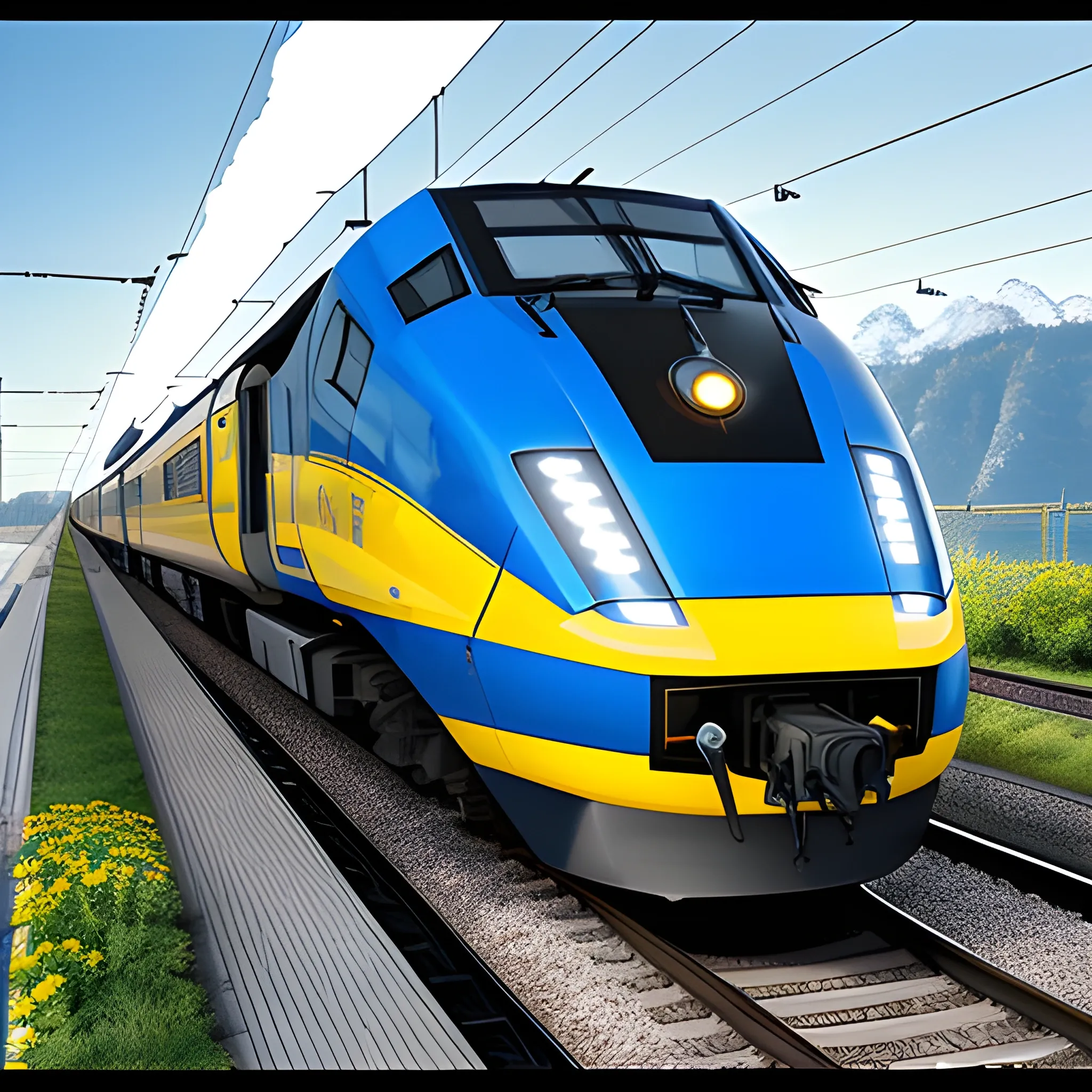
On the vivid image , a state-of-the-art electric locomotive gleams under the bright sunlight. The sleek , futuristic design of the train is highlighted by its polished silver exterior and vibrant LED lights that run along its length. The locomotive is speeding along a modern railway track , surrounded by picturesque landscapes of rolling hills and blooming wildflowers. The electric power lines overhead add a dynamic element to the scene , showcasing the advanced technology that powers this impressive machine. In the background , a clear blue sky provides a stunning backdrop , emphasizing the energy and vitality of the railway industry. The scene captures the essence of progress and innovation in the world of rail transportation , celebrating the hard work and dedication of railway professionals on their special day. ,