Search Results for cross-sections
Explore AI generated designs, images, art and prompts by top community artists and designers.
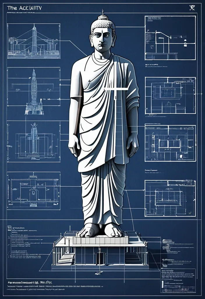

Create an infographic image of The Statue Of Unity(Statue of Unity is the world's tallest statue , with a height of 182 metres , located in Narmada valley , near Kevadia in the state of Gujarat , India) , combining a real photograph of the landmark with blueprint-style technical annotations and diagrams overlaid on the image. Include the title "The Statue Of Unity" in a hand-drawn box in the corner. Add white chalk-style sketches showing key structural data , important measurements , material quantities , internal diagrams , load-flow arrows , cross-sections , floor plans , and notable architectural or engineering features. Style: blueprint aesthetic with white line drawings on the photograph , technical/architectural annotation style , educational infographic feel. ,

A detailed gift certificate for a woman , offering free psychiatric care. The design is a satirical and slightly surreal take on psychiatry , but the certificate itself feels serious and valuable. The style is a mix of vintage medical illustration and modern minimalism. Visual Details: - Layout & Frame: An ornate border with patterns reminiscent of vintage medical diagrams (e.g. , labeled brain cross-sections , tiny neurons , schematic couches). The central area is clean for text. - Color Palette: Muted , noble tones. Dusty rose , deep sapphire blue , medical sage green , cream , with gold foil accents. The paper has a subtle aged parchment texture. - Central Satirical Image: A cute , slightly worried woman in a vintage cartoon style is sitting in an oversized , throne-like psychiatrist's couch. A giant brain , drawn in an anatomical style but with a cartoonish friendly face , floats above her like a balloon she is trying to hold onto. A classic psychiatrist's lamp on a side table shines light not on her , but on a tiny cozy house , symbolizing safety. In one corner , a clock's face is replaced by a calendar page showing "December 2025". - Serious Elements: An official-looking embossed seal with text that says "LICENSE" and "APPROVED". A signature line for a doctor. A serial number. !! CRUCIAL TEXT INSTRUCTIONS !! - All text must be in the Russian language (Cyrillic script). - Large header at the top: ПОДАРОЧНЫЙ СЕРТИФИКАТ - Sub-header: На оказание высококачественных психиатрических услуг - Main body text: Предъявительнице сего сертификата предоставляется право на один сеанс профессиональной разборки полетов. Гарантия: ваши тараканы в голове будут приручены , а внутренний ребенок найден и успокоен. - Expiry date (bold): Действителен до 31 декабря 2025 года - Footer: С любовью и заботой о вашем психическом здоровье Technical Specifications: - Aspect Ratio: 3:4 (vertical layout). - Style: Digital painting , vintage medical illustration , satirical art , high detail. - Mood: Ironic visual metaphors combined with the solemnity of an official document. ,
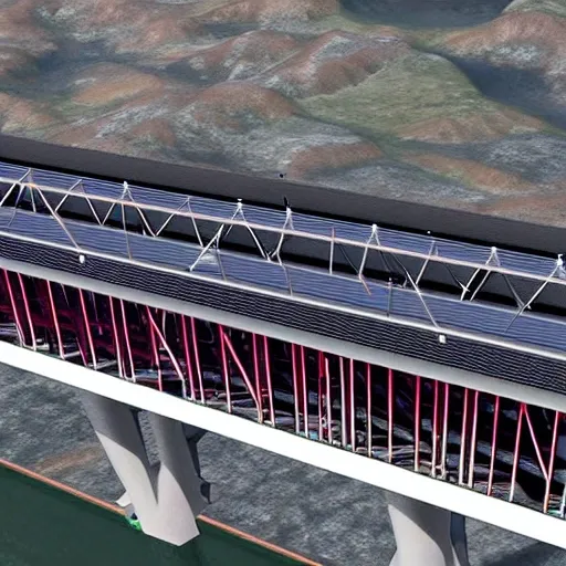
3.Bridge Configuration 1.The bridge may cross the valley at any elevation from the high water level that you can assume to 24 meters above the high water level. 2.If the elevation of the bridge is below 24 meters , excavation of the river banks will be required to achieve the correct highway elevation. 3.To provide clearance for overhead power lines (shown above) , the highest point on the bridge may not exceed an elevation 32.5 meters above the high water level (8.5 meters above the top of the river banks). 4.The bridge may consist of either standard (simple supports) or (arch supports). If necessary , the bridge may also use one intermediate , located near the centre of the valley. If necessary , the bridge may also use cable , located 8 meters behind one or both abutments. 5.Each main truss can have no more than 100 and no more than 200 . 6.The bridge will have a flat , reinforced deck. Two types of concrete are available: 1.Medium-strength concrete requires a deck thickness of 23 centimetres (0.23 metres). 2.High-strength concrete requires a deck thickness of 15 centimetres (0.15 meter). 7.In either case , the deck will be supported by transverse spaced at 4 metre intervals. To accommodate these floor beams , your must have a row of joints spaced 4 meters apart at the level of the deck. These joints are created automatically when you begin a new design. 8.The bridge deck will be 10 meters wide , such that it can accommodate two lanes of traffic. 4.Member Properties •Materials. Each member of the truss will be made of either carbon steel , high-strength low-alloy steel , or quenched and tempered steel. •. The members of the truss can be either solid bars or hollow tubes. Both types of cross-sections are square. •Member Size. Both cross-sections are available in a variety of standard sizes. 5.Loads The bridge must be capable of safely carrying the following loads: •Weight of the deck. •Weight of a 5-cm thick , which might be applied at some time in the future. •Weight of the steel floor beams and supplemental bracing members (assumed to be 12.0 applied at each deck-level joint). •Weight of the main trusses. •Either of two possible truck loadings: Weight of one standard H25 truck loading per lane , including appropriate allowance for the dynamic effects of the moving load. (Since the bridge carries two lanes of traffic , each main truss must safely carry one H25 vehicle , placed anywhere along the length of the deck.) Weight of a single 480 kN Permit Loading , including appropriate allowance for the dynamic effects of the moving load. (Since the Permit Loading is assumed to be cantered laterally , each main truss must safely carry one-half of the total vehicle weight , placed anywhere along the length of the deck.) ,
3.Bridge Configuration 1.The bridge may cross the valley at any elevation from the high water level to 24 meters above the high water level. 2.If the elevation of the bridge is below 24 meters , excavation of the river banks will be required to achieve the correct highway elevation. 3.To provide clearance for overhead power lines (shown above) , the highest point on the bridge may not exceed an elevation 32.5 meters above the high water level (8.5 meters above the top of the river banks). 4.The bridge may consist of either standard (simple supports) or (arch supports). If necessary , the bridge may also use one intermediate , located near the centre of the valley. If necessary , the bridge may also use cable , located 8 meters behind one or both abutments. 5.Each main truss can have no more than 100 and no more than 200 . 6.The bridge will have a flat , reinforced deck. Two types of concrete are available: 1.Medium-strength concrete requires a deck thickness of 23 centimetres (0.23 metres). 2.High-strength concrete requires a deck thickness of 15 centimetres (0.15 meter). 7.In either case , the deck will be supported by transverse spaced at 4 metre intervals. To accommodate these floor beams , your must have a row of joints spaced 4 meters apart at the level of the deck. These joints are created automatically when you begin a new design. 8.The bridge deck will be 10 meters wide , such that it can accommodate two lanes of traffic. 4.Member Properties •Materials. Each member of the truss will be made of either carbon steel , high-strength low-alloy steel , or quenched and tempered steel. •. The members of the truss can be either solid bars or hollow tubes. Both types of cross-sections are square. •Member Size. Both cross-sections are available in a variety of standard sizes. 5.Loads The bridge must be capable of safely carrying the following loads: •Weight of the deck. •Weight of a 5-cm thick , which might be applied at some time in the future. •Weight of the steel floor beams and supplemental bracing members (assumed to be 12.0 applied at each deck-level joint). •Weight of the main trusses. •Either of two possible truck loadings: Weight of one standard H25 truck loading per lane , including appropriate allowance for the dynamic effects of the moving load. (Since the bridge carries two lanes of traffic , each main truss must safely carry one H25 vehicle , placed anywhere along the length of the deck.) Weight of a single 480 kN Permit Loading , including appropriate allowance for the dynamic effects of the moving load. (Since the Permit Loading is assumed to be cantered laterally , each main truss must safely carry one-half of the total vehicle weight , placed anywhere along the length of the deck.) ,
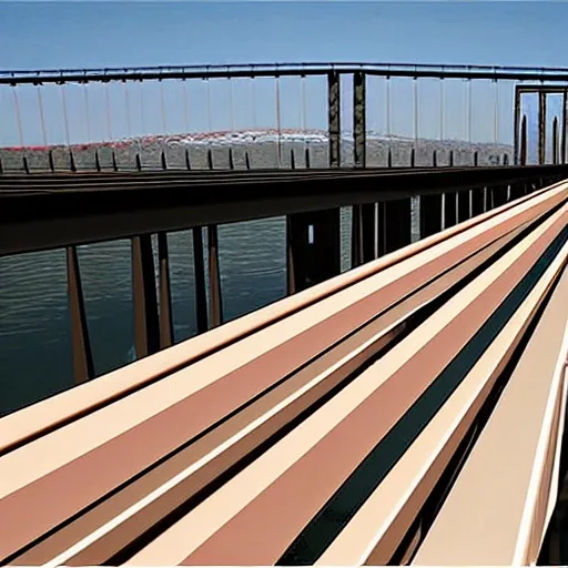
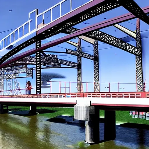
architecture Bridge Configuration 1.The bridge may cross the valley at any elevation from the high water level to 24 meters above the high water level. 2.If the elevation of the bridge is below 24 meters , excavation of the river banks will be required to achieve the correct highway elevation. 3.To provide clearance for overhead power lines (shown above) , the highest point on the bridge may not exceed an elevation 32.5 meters above the high water level (8.5 meters above the top of the river banks). 4.The bridge may consist of either standard (simple supports) or (arch supports). If necessary , the bridge may also use one intermediate , located near the centre of the valley. If necessary , the bridge may also use cable , located 8 meters behind one or both abutments. 5.Each main truss can have no more than 100 and no more than 200 . 6.The bridge will have a flat , reinforced deck. Two types of concrete are available: 1.Medium-strength concrete requires a deck thickness of 23 centimetres (0.23 metres). 2.High-strength concrete requires a deck thickness of 15 centimetres (0.15 meter). 7.In either case , the deck will be supported by transverse spaced at 4 metre intervals. To accommodate these floor beams , your must have a row of joints spaced 4 meters apart at the level of the deck. These joints are created automatically when you begin a new design. 8.The bridge deck will be 10 meters wide , such that it can accommodate two lanes of traffic. 4.Member Properties •Materials. Each member of the truss will be made of either carbon steel , high-strength low-alloy steel , or quenched and tempered steel. •. The members of the truss can be either solid bars or hollow tubes. Both types of cross-sections are square. •Member Size. Both cross-sections are available in a variety of standard sizes. ,
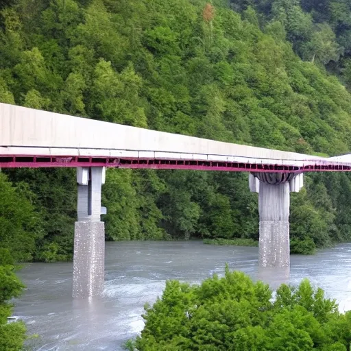
Bridge Configuration 1.The bridge may cross the valley at any elevation from the high water level to 24 meters above the high water level. 2.If the elevation of the bridge is below 24 meters , excavation of the river banks will be required to achieve the correct highway elevation. 3.To provide clearance for overhead power lines (shown above) , the highest point on the bridge may not exceed an elevation 32.5 meters above the high water level (8.5 meters above the top of the river banks). 4.The bridge may consist of either standard (simple supports) or (arch supports). If necessary , the bridge may also use one intermediate , located near the centre of the valley. If necessary , the bridge may also use cable , located 8 meters behind one or both abutments. 5.Each main truss can have no more than 100 and no more than 200 . 6.The bridge will have a flat , reinforced deck. Two types of concrete are available: 1.Medium-strength concrete requires a deck thickness of 23 centimetres (0.23 metres). 2.High-strength concrete requires a deck thickness of 15 centimetres (0.15 meter). 7.In either case , the deck will be supported by transverse spaced at 4 metre intervals. To accommodate these floor beams , your must have a row of joints spaced 4 meters apart at the level of the deck. These joints are created automatically when you begin a new design. 8.The bridge deck will be 10 meters wide , such that it can accommodate two lanes of traffic. 4.Member Properties •Materials. Each member of the truss will be made of either carbon steel , high-strength low-alloy steel , or quenched and tempered steel. •. The members of the truss can be either solid bars or hollow tubes. Both types of cross-sections are square. •Member Size. Both cross-sections are available in a variety of standard sizes. ,