Search Results for in the future
Explore AI generated designs, images, art and prompts by top community artists and designers.


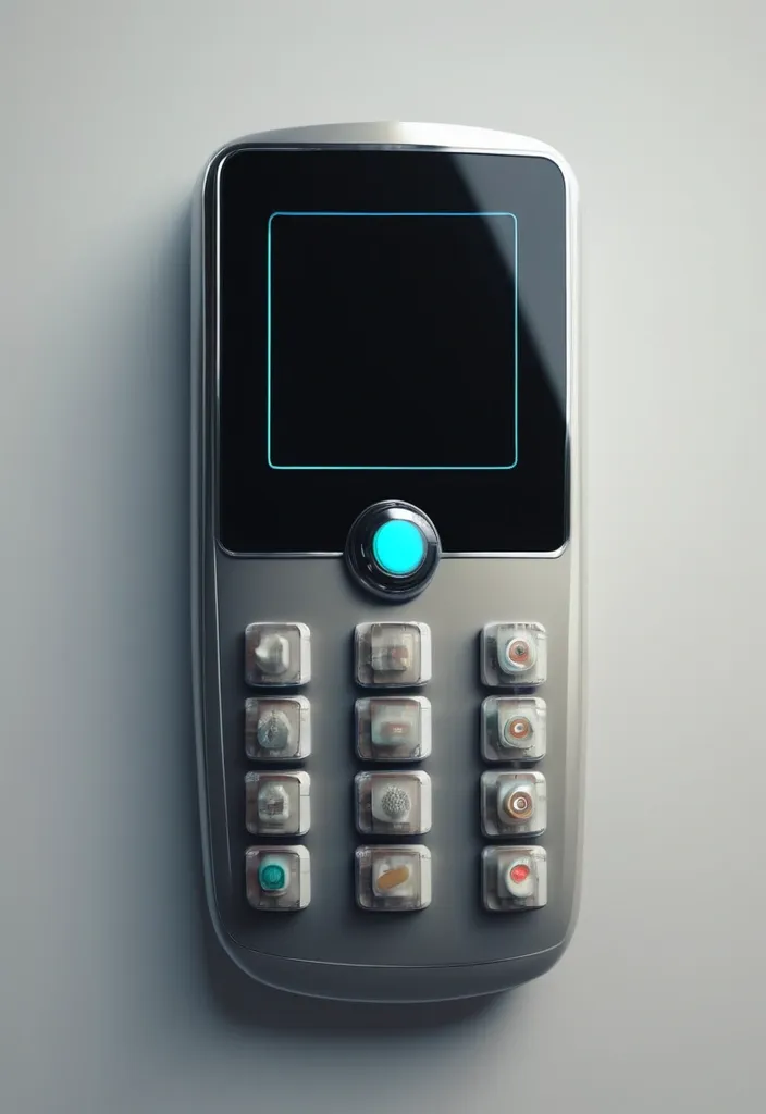
A person holding a futuristic transparent style cell phone with an image of the Facebook home page showing the profile photo of a handsome Musilman man with the username "LISHOTA" , photorealistic-n 9 , very aesthetic , phone in hand , holographic interface , in the future , Very accurate photo , in the near future , the iOS 3D interface design by Jony Ive , in the background is written "KHALIDONET". hyperrealistic photo. Manos de cinco dedos. ,

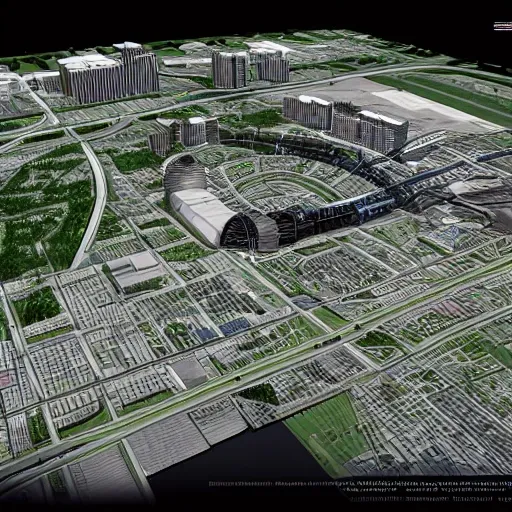
Spiral shaped audience seating: The audience seating is no longer symmetrical circular or fan-shaped , but extends outward from the central stage in a spiral shape , like a flowing olive branch. The spiral design breaks the traditional viewing relationship , allowing the audience to watch the performance from different angles and heights , and gain a unique visual experience. Distributed stage: The stage is no longer limited to a fixed area , but is dispersed at various nodes of the spiral shaped audience seating. Actors can perform on different stages , and audiences can follow in their footsteps and freely move around the theater to experience different plot developments. Immersive Landscape: Olive trees and other Mediterranean plants are planted in the theater , creating a natural landscape barrier and interactive space. Viewers can rest under the shade of trees or interact with plants to become a part of the performance. Modular structure: Spiral foundation module: composed of prefabricated concrete components , forming a spiral foundation structure. Each component is approximately 2 meters long , 0.5 meters wide , and 0.3 meters high , with a moderate weight for easy transportation and installation. Modular platform: Each spiral node is equipped with a modular platform that can serve as a stage or audience seat. The platform is composed of lightweight steel structures and wooden boards , which can be quickly built and dismantled. Removable seats: The seats are made of lightweight materials and can be freely moved and combined to meet different performance needs. Ecological Landscape Module: Install an ecological landscape module on each spiral node , planting olive trees or other Mediterranean plants. The module is made of recyclable materials for easy maintenance and replacement. Featured features: Top view: The theater is spiral shaped with a circular pool in the center , and a statue of the Virgin Mary stands in the center of the pool. The spiral shaped audience seats extend outward from the pool , with a modular platform and ecological landscape module set up at each node. Side view: The theater is in a stepped shape , with spiral shaped audience seats gradually rising , providing a good view for the audience. The modular platform and ecological landscape modules are arranged in a staggered manner between the audience seats. Perspective view: Viewers can freely move on the spiral shaped audience seats and watch the performance from different angles. Actors perform on different modular platforms and interact with the audience. Olive trees and other Mediterranean plants add a natural atmosphere to the theater. The breakthrough modular outdoor theater of "Olive Branch and Our Lady's Song" will become a new trend in the future development of outdoor theaters with its unique design concept and breakthrough layout , providing people with more opportunities to experience art , get close to nature , and experience culture ,
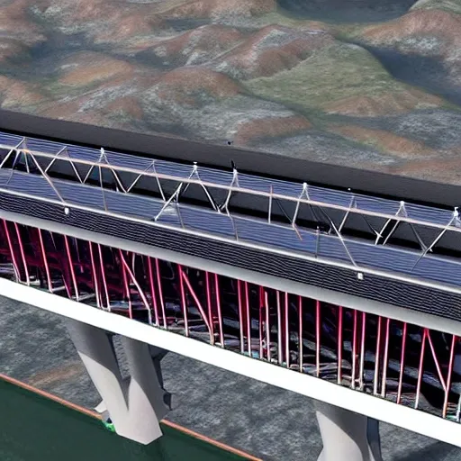
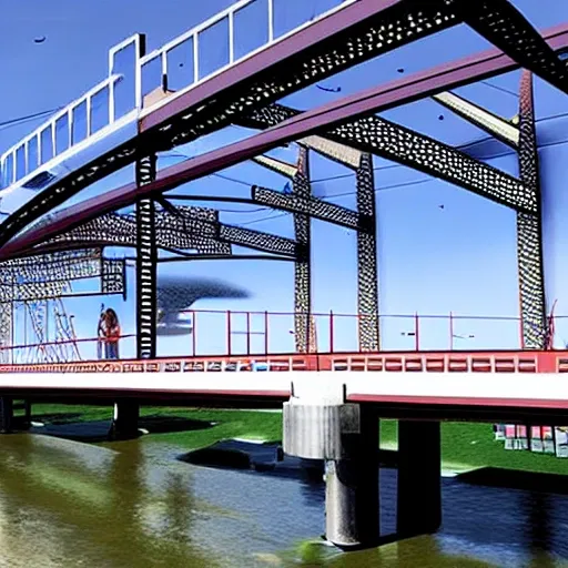
3.Bridge Configuration 1.The bridge may cross the valley at any elevation from the high water level that you can assume to 24 meters above the high water level. 2.If the elevation of the bridge is below 24 meters , excavation of the river banks will be required to achieve the correct highway elevation. 3.To provide clearance for overhead power lines (shown above) , the highest point on the bridge may not exceed an elevation 32.5 meters above the high water level (8.5 meters above the top of the river banks). 4.The bridge may consist of either standard (simple supports) or (arch supports). If necessary , the bridge may also use one intermediate , located near the centre of the valley. If necessary , the bridge may also use cable , located 8 meters behind one or both abutments. 5.Each main truss can have no more than 100 and no more than 200 . 6.The bridge will have a flat , reinforced deck. Two types of concrete are available: 1.Medium-strength concrete requires a deck thickness of 23 centimetres (0.23 metres). 2.High-strength concrete requires a deck thickness of 15 centimetres (0.15 meter). 7.In either case , the deck will be supported by transverse spaced at 4 metre intervals. To accommodate these floor beams , your must have a row of joints spaced 4 meters apart at the level of the deck. These joints are created automatically when you begin a new design. 8.The bridge deck will be 10 meters wide , such that it can accommodate two lanes of traffic. 4.Member Properties •Materials. Each member of the truss will be made of either carbon steel , high-strength low-alloy steel , or quenched and tempered steel. •. The members of the truss can be either solid bars or hollow tubes. Both types of cross-sections are square. •Member Size. Both cross-sections are available in a variety of standard sizes. 5.Loads The bridge must be capable of safely carrying the following loads: •Weight of the deck. •Weight of a 5-cm thick , which might be applied at some time in the future. •Weight of the steel floor beams and supplemental bracing members (assumed to be 12.0 applied at each deck-level joint). •Weight of the main trusses. •Either of two possible truck loadings: Weight of one standard H25 truck loading per lane , including appropriate allowance for the dynamic effects of the moving load. (Since the bridge carries two lanes of traffic , each main truss must safely carry one H25 vehicle , placed anywhere along the length of the deck.) Weight of a single 480 kN Permit Loading , including appropriate allowance for the dynamic effects of the moving load. (Since the Permit Loading is assumed to be cantered laterally , each main truss must safely carry one-half of the total vehicle weight , placed anywhere along the length of the deck.) ,


3.Bridge Configuration 1.The bridge may cross the valley at any elevation from the high water level to 24 meters above the high water level. 2.If the elevation of the bridge is below 24 meters , excavation of the river banks will be required to achieve the correct highway elevation. 3.To provide clearance for overhead power lines (shown above) , the highest point on the bridge may not exceed an elevation 32.5 meters above the high water level (8.5 meters above the top of the river banks). 4.The bridge may consist of either standard (simple supports) or (arch supports). If necessary , the bridge may also use one intermediate , located near the centre of the valley. If necessary , the bridge may also use cable , located 8 meters behind one or both abutments. 5.Each main truss can have no more than 100 and no more than 200 . 6.The bridge will have a flat , reinforced deck. Two types of concrete are available: 1.Medium-strength concrete requires a deck thickness of 23 centimetres (0.23 metres). 2.High-strength concrete requires a deck thickness of 15 centimetres (0.15 meter). 7.In either case , the deck will be supported by transverse spaced at 4 metre intervals. To accommodate these floor beams , your must have a row of joints spaced 4 meters apart at the level of the deck. These joints are created automatically when you begin a new design. 8.The bridge deck will be 10 meters wide , such that it can accommodate two lanes of traffic. 4.Member Properties •Materials. Each member of the truss will be made of either carbon steel , high-strength low-alloy steel , or quenched and tempered steel. •. The members of the truss can be either solid bars or hollow tubes. Both types of cross-sections are square. •Member Size. Both cross-sections are available in a variety of standard sizes. 5.Loads The bridge must be capable of safely carrying the following loads: •Weight of the deck. •Weight of a 5-cm thick , which might be applied at some time in the future. •Weight of the steel floor beams and supplemental bracing members (assumed to be 12.0 applied at each deck-level joint). •Weight of the main trusses. •Either of two possible truck loadings: Weight of one standard H25 truck loading per lane , including appropriate allowance for the dynamic effects of the moving load. (Since the bridge carries two lanes of traffic , each main truss must safely carry one H25 vehicle , placed anywhere along the length of the deck.) Weight of a single 480 kN Permit Loading , including appropriate allowance for the dynamic effects of the moving load. (Since the Permit Loading is assumed to be cantered laterally , each main truss must safely carry one-half of the total vehicle weight , placed anywhere along the length of the deck.) ,