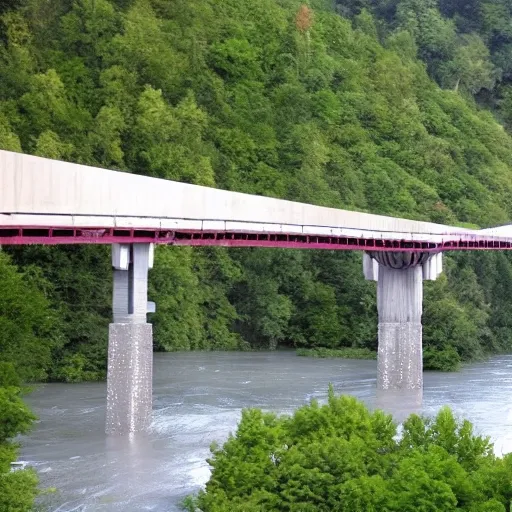
Bridge Configuration 1.The bridge may cross the valley at any elevation from the high water level to

Bridge Configuration 1.The bridge may cross the valley at any elevation from the high water level to 24 meters above the high water level. 2.If the elevation of the bridge is below 24 meters , excavation of the river banks will be required to achieve the correct highway elevation. 3.To provide clearance for overhead power lines (shown above) , the highest point on the bridge may not exceed an elevation 32.5 meters above the high water level (8.5 meters above the top of the river banks). 4.The bridge may consist of either standard (simple supports) or (arch supports). If necessary , the bridge may also use one intermediate , located near the centre of the valley. If necessary , the bridge may also use cable , located 8 meters behind one or both abutments. 5.Each main truss can have no more than 100 and no more than 200 . 6.The bridge will have a flat , reinforced deck. Two types of concrete are available: 1.Medium-strength concrete requires a deck thickness of 23 centimetres (0.23 metres). 2.High-strength concrete requires a deck thickness of 15 centimetres (0.15 meter). 7.In either case , the deck will be supported by transverse spaced at 4 metre intervals. To accommodate these floor beams , your must have a row of joints spaced 4 meters apart at the level of the deck. These joints are created automatically when you begin a new design. 8.The bridge deck will be 10 meters wide , such that it can accommodate two lanes of traffic. 4.Member Properties •Materials. Each member of the truss will be made of either carbon steel , high-strength low-alloy steel , or quenched and tempered steel. •. The members of the truss can be either solid bars or hollow tubes. Both types of cross-sections are square. •Member Size. Both cross-sections are available in a variety of standard sizes. ,
{ "seed": "2378826153", "steps": 30, "width": 512, "height": 512, "version": "SD1.4_SH", "sampler_name": "k_dpm_2", "guidance_scale": 7.5 }
Created on: 5/16/2023, 2:31:49 PM