A detailed technical illustration that shows the two key stages of an oil well operation using a mod

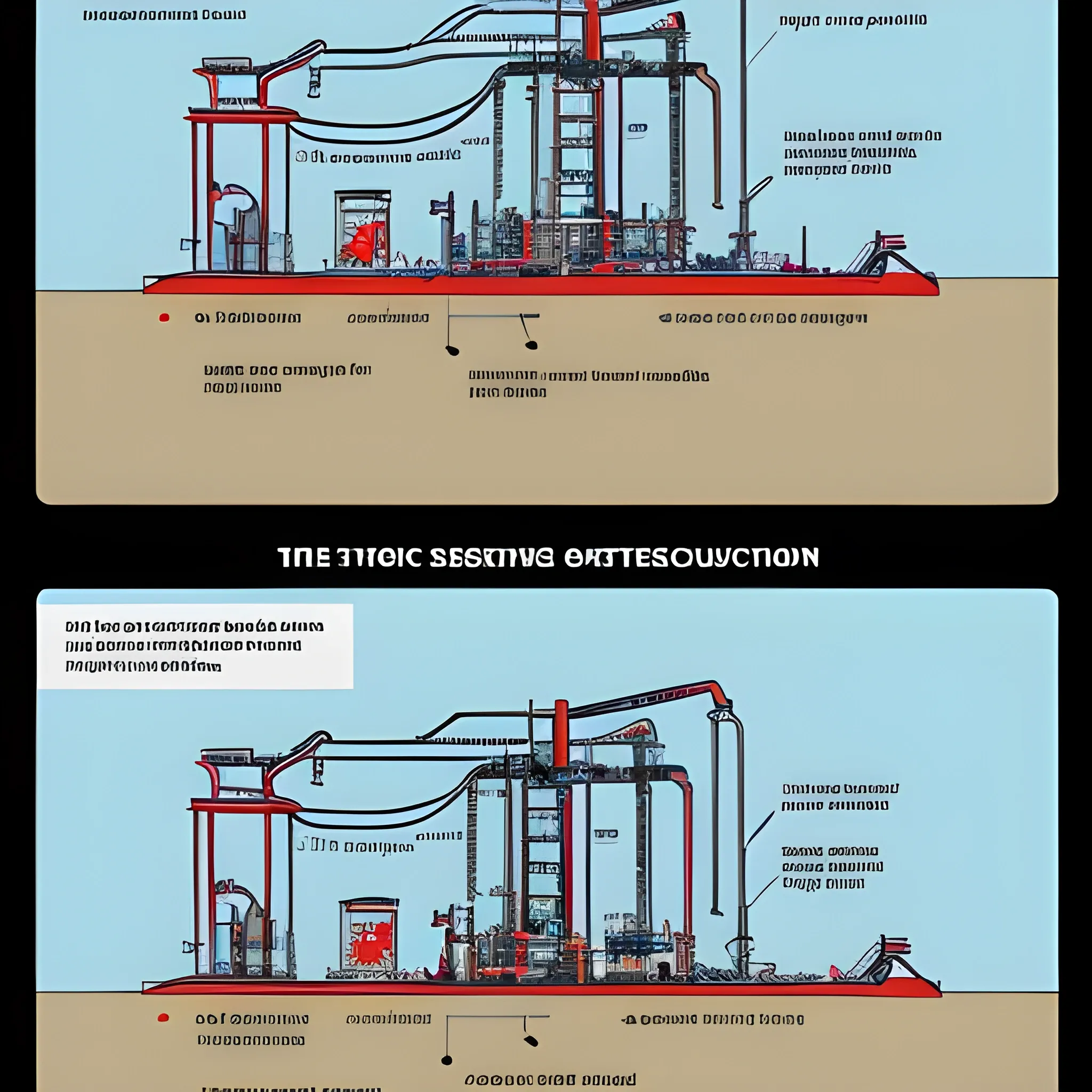
A detailed technical illustration that shows the two key stages of an oil well operation using a modern and clear visual presentation. The left side shows the 'Coolant Injection' process. On the surface is a pump jack , which is commonly used in the oil industry to move fluid out of the well. The red arrows in the illustration highlight the key stages in the process. The first stage is the plunger lift , which plays a vital role in the pump's operation. This process is achieved by lifting the plunger inside the pumping equipment in preparation for injection. The second stage is the securing of the tubing string to the hanger plug. This is an important step to ensure the well is temporarily shut in and prevent unwanted release of contents while preparations are made for the injection of coolant. Below ground , the diagram shows the components such as the tubing string and working rods that are involved in this process. The entire system is shown in section to show how it works in real life and to provide a better understanding of the interactions of the equipment during coolant injection. The right side of the illustration shows the 'Transition to Production' process. Again , the pump jack is shown on the surface , but now the focus is on the process of oil extraction. Arrows point to several important operations. First , the solid ring is removed to prepare the well for operation. Next comes the installation of the polished rod , which is an important element of the pumping system and allows for the efficient transfer of forces for the pump to operate. Finally , the process of lowering the plunger , which initiates the operation of the system in the production mode , is shown. A schematic representation of the underground part of the well in section shows how the elements of the pumping system work during oil extraction. In particular , equipment such as the SPR-57 cylinder and plunger , which are used to ensure oil extraction , are highlighted. All elements are provided with clear labels and descriptions , which makes it easier to understand the processes and equipment. The illustration is made in a modern style with clear lines and bright colors to simplify the perception of complex technical processes. All key operations are provided with explanatory arrows , and the captions help to quickly navigate what actions are performed at each stage. The equipment , both on the surface and underground , is shown in cross-section , which provides a more complete understanding of all stages of the well operation. The illustration is suitable for use in training and working materials in the oil and gas industry , as it provides a visual and understandable idea of the process of pumping coolant and subsequent oil production ,
{ "seed": "2317003073", "steps": 30, "width": 512, "height": 512, "version": "SH_Deliberate", "sampler_name": "k_dpm_2", "guidance_scale": 7.5 }
Created on: 10/5/2024, 12:07:54 PM